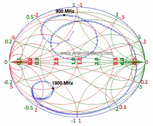
Figure 18 shows how inductors and capacitors can be used to change the impedance.
#Antenna smith chart series
Capacitors and inductors in series or parallel can be used to match the antenna to the desired impedance. If varying these factors is not possible or if the performance still needs to be improved, discreet components could be used to optimize the impedance. Thus by varying these factors it might be possible to improve the impedance match of the antenna. Size of ground plane, distance from antenna to ground plane, dimensions of antenna elements, feed point, and plastic casing are factors that can affect the impedance. For example, the normalized impedance for a loadZ L 73 + j42 on a50 transmission line isZ LN 1.46 + j0. matching network for a high Q antenna can lead to performance issues that are caused. Corresponding to loop on smith chart, plot on VSWR is less than 2 ,which is bandwidth of the antenna which has appeared only due to coupling and is absent. The Smith Chart works with normalized impedance and admittance, where normalization is made with respect to the characteristicimpedance of the transmission line. Figure 4 shows the smith chart 5 of the praposed Microstrip Yagi Uda antenna, Impedance matching is analyzed by investigating the Smith chart of antenna it shows that the impedance of the antenna. from publication: Coplanar Waveguide Fed Compact Wide Circular-Slotted Antenna for Wi-Fi/WiMAX.
#Antenna smith chart download
Dependent of the antenna type there are several possibilities to obtain optimum impedance at the correct frequency. tions with the aid of VSWR, reflection coefficient, and Smith chart. Download scientific diagram Proposed antenna (a), Smith chart, and (b) input impedance. If the resonance frequency is too high, the antenna length should be increased.Įven if the antenna resonates at the correct frequency it might not be well matched to the correct impedance. Having recently acquired a programmable calculator. Thus if the resonance frequency is to low, the antenna should be made shorter. In January 1977 there appeared in RADCOM an article by G6XN extolling the virtues of the Smith Chart. What is a Smith chart Its really just a plot of complex reflection overlaid with an impedance and/or admittance grid referenced to a 1-ohm characteristic. Ideally the frequency which gives least reflection should be in the middle of the frequency band of interest. For resonant antennas the main factor is the length. There are several ways to tune an antenna to achieve better performance. especially built-in antennas, such as spring type, chip type, pcb or fpc type antenna.

To be precise, all antennas need impedance matching when applied to products. Antenna Matching is very important work in client side, not only antenna supplier side.


 0 kommentar(er)
